
Combustion Basics
Combustion occurs when fossil fuels react to oxygen in the air to produce heat. Fossil fuels are hydrocarbons, meaning they are composed primarily of carbon and hydrogen. When fossil fuels are burned, carbon dioxide (CO2) and water (H2O) are the principal chemical products formed from the reactants carbon and hydrogen in the fuel and oxygen in the air.
The simplest example of hydrocarbon fuel combustion is the reaction of methane (CH4), the largest component of natural gas, with O2 in the air.
When this reaction is balanced, or stoichiometric, each molecule of methane reacts with two molecules of O2 producing one molecule of CO2 and two molecules of H2O. When this occurs, energy is released as heat.
CH4 + 2 O2 => CO2 + 2 H2O
Reactants => Products + Heat
In actual combustion processes, other products are often formed.
A typical example of an actual combustion process is shown in Figure 1. Fuel has reacted with air to produce the products shown on the right.
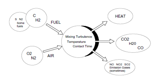
Figure 1: Combustion diagram
The combining of oxygen in the air and carbon in the fuel to form carbon dioxide and generate heat is a complex process. The process requires:
– The right mixing turbulence,
– Sufficient activation temperature,
– Enough time for the reactants to come into contact and combine.
Unless combustion is properly controlled, high concentrations of undesirable products can form:
– Carbon monoxide (CO) and soot, for example, result from poor fuel and air mixing or too little air.
– Other undesirable products, such as nitrogen oxides (NO, NO2), form in excessive amounts when the burner flame temperature is too high.
If a fuel contains sulfur, sulfur dioxide (SO2) gas is formed.
For solid fuels such as coal and wood, ash forms from incombustible materials in the fuel.
Combustion Analysis
Combustion analysis is part of a process intended to improve fuel economy, reduce undesirable exhaust emissions and improve the safety of fuel burning equipment.
Combustion analysis begins with the measurement of flue gas concentrations and gas temperature, and may include the measurement of draft pressure and soot level.
– To measure gas concentration, a probe is inserted into the exhaust flue and a gas sample drawn out.
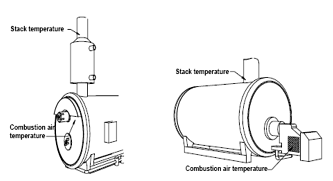
– Exhaust gas temperature is measured using a thermocouple positioned to measure the highest exhaust gas temperature.
– Soot (black smoke) is measured from a gas sample drawn off the exhaust flue.
– Draft is the differential pressure between the inside and outside of the exhaust flue.
Once these measurements are made, the data is interpreted using calculated combustion parameters such as combustion efficiency and excess air. A more in depth analysis will examine the concentration of the undesirable products described earlier.
Improving Fuel Efficiency
The largest sources of boiler heat losses are shown Figure 2.

Figure 2. Boiler Heat Losses
Heat energy leaving the system exhaust flue (or stack) is often the largest single source of lost fuel energy and is made up of the Dry Gas loss and Latent Heat Loss. Although some flue loss is unavoidable, an equipment tune-up using combustion analysis data can often significantly reduce this source of heat loss and save fuel costs by improving fuel efficiency.
Losses and energy efficiency
One of the most important application of combustion analysis is the energy saving. Standards are requesting that every installation has to be controlled on an efficiency point of view.
Efficiency is defined as a ratio between heating transferred to water to heat it and heat generated to boiler.
Example
Boiler:
– 20.000kcal/hour
– 10 liter/minute. Temperature difference of 30°C
Water uses 300kCal/minutes equivalent to 18.000kCal/hour
Efficiency is (18.000 / 20.000).

Combustion efficiency
Efficiency = 100 – Qs (Loss in stack)
Loss in the stack
Qs = k * (Tg – Ta) / CO2
· Qs Loss in stack
· K relative to combustible
· Tg Gas Temperature
· Ta Air temperature
· CO2 % CO2
The solution to improve efficiency is to have the highest CO2 value, then to optimize combustion: it the role of excess air.
Reduce Emissions
Carbon monoxide, sulfur dioxide, nitrogen oxides and particles are undesirable emissions associated with burning fossil fuels. These compounds are toxic, contribute to acid rain and smog and can ultimately cause respiratory problems. State laws govern the permissible emission rates for these pollutants.
Combustion analysis is performed to monitor toxic and acid rain forming emissions in order to meet these state and local regulations.
Improving Safety
Good equipment maintenance practice, which includes combustion analysis, enables the boiler technician to fully verify and maintain the equipment operating specifications for safe and efficient operation.
Improve Safety – Excess Air
Many boiler manufacturers suggest that flue gas analysis be performed at least monthly. Boiler adjustments that affect combustion will tend to drift with time. Wind conditions and seasonal changes in temperature and barometric pressure can cause the excess air in a system to fluctuate several percent. A reduction in excess air can cause, in turn, a rapid increase of highly toxic carbon monoxide and explosive gases, resulting in rapid deterioration in system safety and efficiency.
Figure shows the evolution of composition of smokes relative to excess air. When O2 is missing, CO is produced. When excess air increases above a value, C02 is diluted, then combustion efficiency decreases.

When combustion is performed without enough oxygen, we can talk about incomplete combustion. Then soot is produced, and CO is present.
CO Is a very dangerous gas: Human nose cannot detect it, it goes in the blood, is fixed in place of oxygen, and avoid the transportation of oxygen to cells (Muscle, brain, heart°. A value of 0,2% of CO will produce death in less than 30 minutes.
External conditions (Wind, atm pressure, external temperature, will contribute to a phenomenon called “excess air reduction”.
Excess air reduction will be traduced by increase of CO, and explosive gas that can produce safety system failure, and efficiency loss.
Improve Safety – Draft
Low draft pressures in the flue can further result in these combustion gases building up in the combustion chamber or being vented indoors. Excessive draft pressures in the flue also can cause turbulence in the system. This can prevent complete combustion and pull explosive gases into the flue or cause flame impingement and damage in the combustion chamber and to the heat exchanger material.
What’s measured?
Combustion analysis involves the measurement of gas concentrations, temperatures and pressure for boiler tune-ups, emissions checks and safety improvements. Parameters that are commonly examined include:
– Oxygen (O2)
– Carbon Monoxide (CO)
– Carbon Dioxide (CO2)
– Exhaust gas temperature
– Supplied combustion air temperature
– Draft
– Nitric Oxide (NO)
– Nitrogen Dioxide (NO2)
– Sulfur Dioxide (SO2)
Measurement Tools
· Manual Gas Measurements
· Portable Electronic Instruments
· Continuous Emission Monitors
Manual Gas Measurements
The Orsat analyzer is a gas concentration analysis tool typically used to manually sample CO2, O2 and CO from the flue of a combustion system. The Orsat analyzer determines the gas concentrations from a sample of gas extracted from the flue and bubbled through solutions of reagents that selectively absorb each gas. By measuring the decrease in gas volume over the liquid reagents, the amount of gas absorbed is indicated. From this information, stack gas concentration is calculated. Manual gases measurements are time consuming and do not accurately reflect real-time adjustments made to a system.
Portable Electronic Instruments
In recent years, electronic instruments such as the GreenLine 8000 Combustion Analyzer have been developed to analyze combustion routinely for tune-ups, maintenance and emissions monitoring.
These instruments are extractive. They remove a sample from the stack or flue with a vacuum pump and then analyze the sample using electrochemical gas sensors. Today Non Dispersive Infrared Sensor (NDIR) can be included in one portable unit.
Thermocouples are used for stack and combustion air temperature measurements, and a pressure transducer is used for the draft measurement. An on-board computer performs the common combustion calculations, eliminating the need to use tables or perform tedious calculations. Electronic instruments show the results of boiler adjustments in real-time and give more accurate information to help ensure that a system has been tuned properly.
Continuous Emission Monitors
Continuous emission monitors, or CEMS, are a class of electronic instruments designed to measure exhaust stack gases and temperature continuously. CEMs are sometimes used for combustion control, but typically are used for monitoring pollutant gas emissions as required by government regulations. CEMs can use both extractive and in-situ (sensors in the stack) sampling methods, and employ a variety of electronic sensor technologies for gas detection. CEMs are used most often on larger installations or when required by regulatory agencies.
Using Measurements
Once flue gas and temperature measurements are made, combustion parameters are calculated to help evaluate the operating performance of the furnace or boiler. Typical combustion parameters include:
– Excess Air
– Carbon Dioxide
– Combustion Efficiency
– O2 Reference
– Emissions Conversions
Excess Air
Insufficient combustion air causes a reduction in fuel efficiency, creates highly toxic carbon monoxide gas and produces soot.
To ensure there is enough oxygen to completely react with the fuel, extra combustion air is usually supplied. This extra air, called “Excess Air,” is expressed as the percent air above the amount theoretically needed for complete combustion

O2 Reference
Excess air is supplied to the combustion process to ensure that there is enough oxygen to completely react with the fuel. Excess air is measured in the flue as a percentage of O2. This excess air dilutes the concentration of other gases measured.
Local regulatory agencies have guidelines for monitoring NO, NO2, CO, and SO2 gases. Generally, it is required that the concentration of these gases be corrected for the diluting effects of excess air. The measured O2concentration, together with the O2 reference value is used in the equation below to obtain the corrected gas concentration.

Making Measurements
· Taking Gas Samples
· Making Temperature and Draft Measurements
· Soot Measurements
Taking Gas Samples
To get the most accurate measurement, the gas sampling probe must be placed prior to any draft damper or diverter, so that the gases are not diluted, and as close to the equipment breach as possible so the gases have not cooled in the flue. If there is a stack economizer or similar device, the measurement should be taken just downstream of the installed device.

Making Temperature and Draft Measurements
This thermocouple probe is placed at the point of highest exhaust gas temperature at the base of the flue and toward the center for small ducts. If the stack gas temperature is underestimated, the operating efficiency will be overstated.

Soot Measurements
Soot is most commonly measured during equipment tune-up and maintenance by extracting a sample of the exhaust gases using a manual sampling pump.
The sample is taken from the same location as the stack temperature measurements
How to measure?


")

 (Model:1260A)")
")


")


